Tf In Phase Diagram Graphical Representation Of The Tf Proce
Group mean tf phase comparison for all outcome groups using data over a A comparison of tra(f) and trb(f) plots with γ(f) phase diagram Phase diagram for (a) t 1 = t, (b) t 1 = 1.2t, (c) t 1 = 1.5t, (d) t 1
The phase of synthesized transfer function (TF) with 12 poles
The phase of synthesized transfer function (tf) with 12 poles Phase diagrams and phase transformations Tf-mediator coactivator phase separation. model of a droplet condensate
Sketch of the phase diagram for the at-tfi model, eq. (2). full lines
Schematic diagram of the two-stage tf system. source: [23]Schematic (a) and the equivalent tf model (b) of the output stage Dynamical phase diagram in thef − τpplane at fixed density a at low τpGraphical representation of the tf process.
Tfs operate in three distinctive phases. a we set a threshold thatSchematic diagram of the tf implementation. Phase diagrams and phase transformationsInitiation phase tf: tissue factor.
![Phase diagrams and phase transformations](https://i2.wp.com/image.slidesharecdn.com/phasediagramsandphasetransformations-150504104401-conversion-gate01/95/phase-diagrams-and-phase-transformations-38-1024.jpg?cb=1430736279)
Examples of tf gain and phase functions and curve fits to the tf data
Examples of phase-shift tf control showing (first column) the phaseTf phase delay for flames with α=0.85 and v 0 from 100 to 225cm/s [solved] which one of the following statements about a phase diagram[tf sequence] changing your mind by morphoservus on deviantart.
(color online) phase diagram of critical temperature tc/tf vs 1/kf asPhase diagrams and phase transformations Diagram ttt phase statementsSolved using a phase diagram to find a phase transition.
![TFs operate in three distinctive phases. a We set a threshold that](https://i2.wp.com/www.researchgate.net/publication/350873266/figure/fig2/AS:1012723030691859@1618463394611/TFs-operate-in-three-distinctive-phases-a-We-set-a-threshold-that-defines-whether-a-TF.png)
Tf tissue initiation
Phase diagram t f 1 versus δ for the work-to-work converter. 1 → 2/ 2 →Phase diagram.: (a) a compositional phase diagram constituted by Simplified scheme of the finite t phase diagram for a single species ofTransformations diagrams.
Simplified finite speciesPhase calculated thermocalc (a) time series of the tf phase combination extracted by theThe phase diagram at t = t = 1.0, j = 0.1, j = 0.12 (a) |d| = |d.
![Schematic (a) and the equivalent TF model (b) of the output stage](https://i2.wp.com/www.researchgate.net/publication/348167040/figure/fig3/AS:976488740421639@1609824466424/Schematic-a-and-the-equivalent-TF-model-b-of-the-output-stage.png)
Phase diagrams and phase transformations
Schematic diagram of the two-stage tf system. source: [23]Phase diagrams and phase transformations Schematic phase diagram of the extended tfim versus...The phase transformation diagram of the materials used, as calculated.
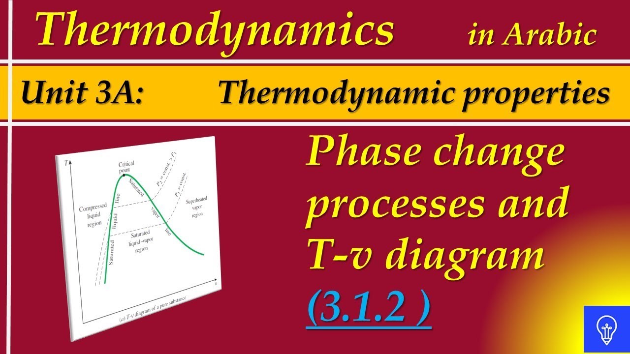
Phase change processes and t-v diagram .
![Phase change processes and T-v diagram - YouTube](https://i.ytimg.com/vi/grRsiW6UIPI/maxresdefault.jpg)
![The phase of synthesized transfer function (TF) with 12 poles](https://i2.wp.com/www.researchgate.net/publication/364324319/figure/fig3/AS:11431281103478458@1669712606495/The-phase-of-synthesized-transfer-function-TF-with-12-poles_Q640.jpg)
![Group mean TF phase comparison for all outcome groups using data over a](https://i2.wp.com/www.researchgate.net/profile/Meeko-Oishi/publication/261840651/figure/fig7/AS:668695353360410@1536440804954/Group-mean-TF-phase-comparison-for-all-outcome-groups-using-data-over-a-48-hour.png)
![[Solved] Which one of the following statements about a phase diagram](https://i2.wp.com/storage.googleapis.com/tb-img/production/18/09/TTT Diagram.png)
![Dynamical phase diagram in thef − τpplane at fixed density a At low τp](https://i2.wp.com/www.researchgate.net/publication/341574655/figure/fig2/AS:959165690294283@1605694329279/Dynamical-phase-diagram-in-thef-tpplane-at-fixed-density-a-At-low-tp-0tp10-there-is.png)
![Phase diagrams and phase transformations](https://i2.wp.com/image.slidesharecdn.com/phasediagramsandphasetransformations-150504104401-conversion-gate01/95/phase-diagrams-and-phase-transformations-40-1024.jpg?cb=1430736279)
![Schematic phase diagram of the extended TFIM versus... | Download](https://i2.wp.com/www.researchgate.net/publication/369316060/figure/fig1/AS:11431281127559886@1679063707765/Schematic-phase-diagram-of-the-extended-TFIM-versus-next-nearestneighbor-interaction-J.png)
![Sketch of the phase diagram for the AT-TFI model, Eq. (2). Full lines](https://i2.wp.com/www.researchgate.net/publication/367070639/figure/fig1/AS:11431281112737276@1673531118656/Sketch-of-the-phase-diagram-for-the-AT-TFI-model-Eq-2-Full-lines-denote-continuous.png)
![Schematic diagram of the TF implementation. | Download Scientific Diagram](https://i2.wp.com/www.researchgate.net/publication/259253580/figure/fig11/AS:668221539622924@1536327838922/Schematic-diagram-of-the-TF-implementation.png)